


Product Details
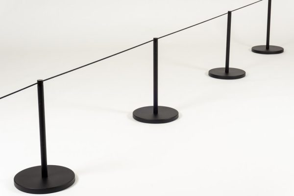
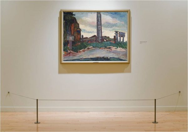
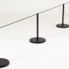
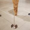
This Gallery barrier is the standard in many of the world’s major museums.
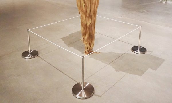
The stable bases and uprights support an elastic cord that defines restricted access but gives to the touch without tripping or injury. The Freestanding base is cushioned with slip resistant polyurethane pads to improve grip and protect polished floor surfaces.
We recommend a maximum of 7 to 8 feet or 2 to 3 meters between barriers when planning your layout.
Things you’ll Need:
- Barriers
- Elastic Cord (75 foot rolls)
- Wall terminators (Possibly)
**Sold individually**
Did you know we manufacture most of our products in New Jersey and our full service shop is always making custom versions of products. If you have any special needs let us know!
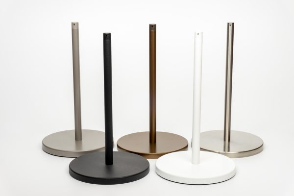
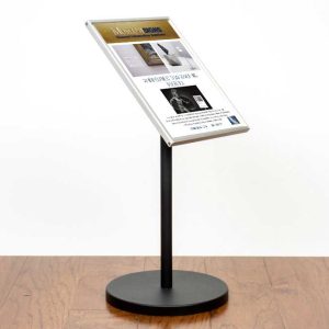
Art Stanchions
From: $115.00
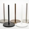
- Neutral, clean lines that blend with the environment
- Stable bases
- Options to accommodate signage and tie-back to wall
- Quantity Break Discounts applied in cart.
- Made in the USA
- Additional Information
- Freestanding
- Surface Mounted
- Wood Floor Socket
- Masonry Socket
- Magnetic
- Other Resources
Additional Information
ACCESSORIES FOR THE FREESTANDING STANCHION
You will require elasticated cord to go with your stanchion layout.
Wall terminators are an excellent way to complete some stanchion installations by returning the line of cord back to the wall.
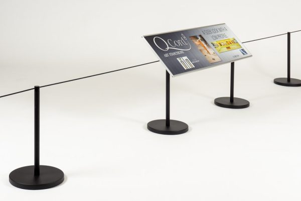
You can now apply information signage directly to the top of our barriers by using one of our signage adaptors that will accept our range of aluminum label holders.
Our stanchions are supplied complete with an Allen key and that is the only tool you will require to assemble them.
USEFUL TIPS AND GUIDELINES
It is important to select a stanchion finish that blends well with the environment and minimizes visual impact, and to assist this process our standard cord color is grey. However, in areas where it is important to draw attention to the line, we can supply cord in a range of colors that will enhance the contrast. These are white, red or black.
If a floor is highly polished the stanchions will need to be closer together (7′) than a floor that has plenty of grip, in which case barriers can be spaced further apart (9′).
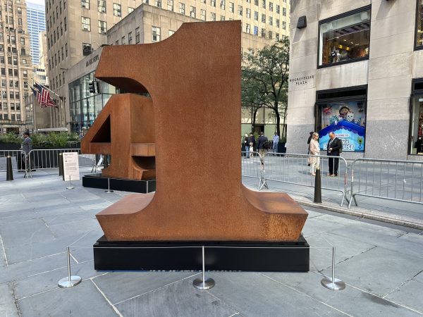
Whenever possible stanchions should be placed in a symmetrical fashion in front of an artwork as this maintains good overall visual harmony.
Freestanding
INSTALLATION INSTRUCTIONS FOR FREESTANDING
Stanchions are sold individually.
- Assemble the barrier by placing the cover over the heavy black baseplate.
- Remove the bolt from the packaging, fit the washer onto the bolt and place it through the central hole of the base plate and cover and into the end of the upright. Tighten securely with the Allen Key provided.
- Place the barriers in position to protect the artwork allowing 6 to 9 feet between each barrier. For the best result be sure to check that the cord does not ‘droop’ between barriers.
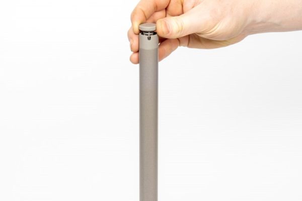
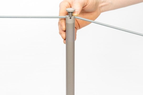
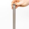
- When you have the desired layout, lift up the top cap and insert the cord.
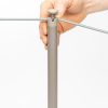
- Insert the end of the cord into the space under the cap and wrap the cord around the stem once or twice and out through one of the slots. Hold the cord in place and push the cap down and twist to lock.
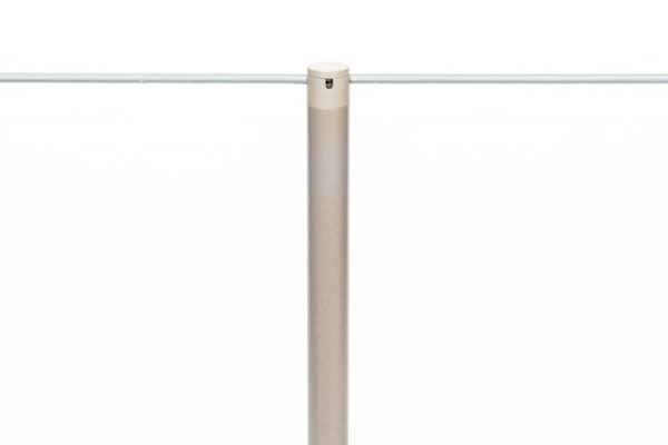
- For intermediate barriers, pull the cord tight to the next barrier with enough tension to make a straight line and feed the cord in through one slot, around the cap stem and out through the appropriate slot. Straight through for a line of barriers and ninety degrees at a corner.
- When the layout is complete, make sure all caps are pushed down correctly so that the cord is secure on the top of the barrier.
A line of barriers can also end with the cord returning to the wall by using a wall terminator.
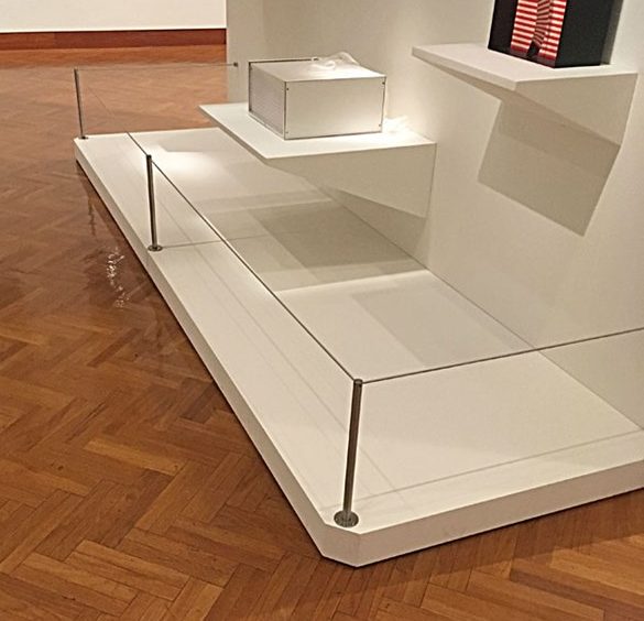
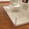
Surface Mounted
This barrier features a base plate that can be screw fixed to the floor. The screws are then concealed beneath the cover plate.
4″ diam. x .25″ base plate with .0625″ cover plate.
The upright supports an elasticated cord that defines restricted access but gives to the touch without tripping or injury.
We recommend a maximum of 10 feet or 3 meters between these barriers.
INSTALLATION INSTRUCTIONS FOR SURFACE MOUNTED
Stanchions are sold individually.
Stanchions are supplied with an Allen key for assembly.
- Screw the base plate to the end of the upright with the countersunk bolt placed through the central hole and tighten securely with the Allen key. The countersink for the three screw holes will be on the top surface of the base plate.
- Mark out the position of the barriers being careful to ensure that the cord slots on top are inline, and screw into place using a #8 size screws or similar. Normal spacing between barriers is 7′- 8′ but this can be increased to 10′ on occasion, so long as the tension on the cord is sufficient to maintain a straight and level line.
- Place the supplied cover plate over the top of the stanchion and slide down to the base so that it hides all of the fixings.
- Twist the cap to open, insert the end of the cord into the space under the cap and wrap the cord around the stem once or twice and out through one of the slots. Hold the cord in place and push the cap down and twist to lock
- Pull the cord tight to the next stanchion with enough tension to make a straight line and push into the slots: straight across if it is a straight line or at right angles if it is at a corner.
A line of stanchions can also end with the cord returning to the wall by using a wall terminator.
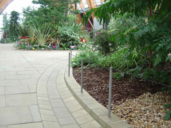
Wood Floor Socket
INSTALLATION INSTRUCTIONS FOR WOOD FLOOR SOCKET
Stanchions are sold individually.
- Mark out the position of the sockets. Normal spacing is approximately 8 Feet between posts, we recommend a maximum of 10 feet or 3 meters between these barriers.
- Drill the holes in the floor surface using an appropriate Auger bit to produce a clean hole approximately 7/8 dia. and at least 2 1/2 deep.
- Place the socket in the hole and mark the screw positions then secure the socket with 4 countersunk #6 screws. Stainless will give the best look but other finishes can be used.
- Attach the Adaptor to the upright with the included cover plate and insert the upright into the socket.
- Twist the cap to open, insert the end of the cord into the space under the cap and wrap the cord around the stem once or twice and out through one of the slots. Hold the cord in place and push the cap down and twist to lock.
- Pull the cord tight to the next stanchion with enough tension to make a straight line and push into the slots: straight across if it is a straight line or at right angles if it is at a corner.
A line of stanchions can also end with the cord returning to the wall by using a wall terminator.
Masonry Socket
INSTALLATION INSTRUCTIONS FOR MASONRY SOCKET
Stanchions are sold individually.
- Mark out the position of the sockets. Normal spacing is approximately 8 Feet between posts, we recommend a maximum of 10 feet or 3 meters between these barriers.
- Drill the holes in the floor surface using an appropriate Masonry bit to produce a clean hole approximately 7/8 dia. and at least 2 1/2 deep.
- Test Fit Sockets and shim as needed
- Apply an appropriate epoxy resin into the bottom and sides of the hole and insert the socket, being sure to ‘bed it down’ by using small backwards and forwards rotational motions to assist the movement of the resin.
- If required carefully apply additional resin to any gap at the top of the socket to ensure that the finish is flush with the floor and clean off any excess resin that squeezes out.
- Insert Posts into the sockets and use a level to check that the upright it is vertical, and if necessary, support in this position while the resin cures.
- Twist the cap to open, insert the end of the cord into the space under the cap and wrap the cord around the stem once or twice and out through one of the slots. Hold the cord in place and push the cap down and twist to lock
- Pull the cord tight to the next stanchion with enough tension to make a straight line and push into the slots: straight across if it is a straight line or at right angles if it is at a corner.
A line of stanchions can also end with the cord returning to the wall by using a wall terminator.
Magnetic
INSTALLATION INSTRUCTIONS FOR MAGNETIC
Stanchions are sold individually.
Note: The adhesive pad included with this product is industrial strength and once applied, cannot be moved or repositioned. Position carefully!
- Prepare the flooring: Smooth surfaces should be wiped clean with isopropyl alcohol. Porous surfaces (wood, particleboard, rough concrete, etc.) need to be sealed to provide a unified surface.
- Watch out for dirty surface (dust, oil, dirt, etc.), temperatures below 50 °F, moisture, and low surface energy materials (silicone paints, slippery plastics, etc.)
- Determine the queue configuration. Position all posts (without the magnetic plate) prior to applying the adhesive and marking the floor for each posts position with a removable mark.
- Remove the protective backing from the adhesive pad on the magnetic plate and place the exposed adhesive onto each spot that has been marked.
- Allow adhesive to cure for 24 hours without the post attached. Adhesive is pressure sensitive so press down firmly, briefly stand on plate, and if possible, apply weight during curing.
- After the cure is complete, determine the cord direction, align base to receiver plate at an angle, and gently rock the post into position.
A line of stanchions can also end with the cord returning to the wall by using a wall terminator.


Related Items
-
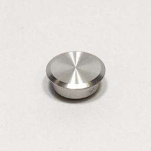
Art Stanchion Socket Cap
$35.00 Add to cart -
Art Stanchion Signage
Price range: $98.50 through $167.00 Select options This product has multiple variants. The options may be chosen on the product page